The Green Hydrogen Lab at VJTI features a highly advanced
grid-connected microgrid system. This microgrid seamlessly integrates multiple
renewable energy sources and energy storage systems, enabling efficient and
sustainable energy management.
A. Key Sources in the Microgrid:
1. Wind
Turbine Emulator: Wind turbine
emulator mimics the behaviour of wind turbine for hardware level simulations.
This system has a DC motor coupled with the Induction generator/Permanent
Magnet Synchronous Generator, speed of which is controlled as per the speed
reference calculated by solving the mathematical model of wind turbine. An
induction generator is coupled to the DC motor and bidirectional inverter is
connected to the terminals of the generator. Researcher can execute the
mathematical models of their newly developed or modified wind turbine and can
simulate the speed/power of profile of turbine on hardware environment directly
for different wind speeds & pitch angle.
2.
PV Emulator: PV Emulator
is a programmable power supply designed to mimic the characteristics of Solar
Panels. With fast transient response, the emulator responds to change in load
conditions and maintains the output on IV characteristics of the panels defined
by user for a given ambient condition.
It is a flexible instrument designed to
emulate the output of solar panels, with adjustable parameters such as Voc,
Isc, shading, coefficient of temperature etc. The PV Emulator uses an internal
algorithm to adjust Voc (Open circuit voltage) and Isc (short-circuit current)
so as to match the solar panel selected by the user based on user defined
parameters such as Irradiation, temperature, Voc, Isc, temperature coefficient
etc. The Emulator makes sure the response matches that of the actual panel
under all the load conditions within range. The user is presented with a
complete set of information with tables and plots on user application.
The software of PV Emulator is based on
Labview. User is able to see the response of Solar PV Panel as per his/her own
set of users defined parameters. User defined parameters involve open circuit
voltage, short circuit current, temperature coefficient, complete shading,
partial shading (up to 4 peaks), series resistance, area of panel, diode
quality factor and operating temperature.
3. Fuel Cell: Fuel Cell unit receives dry hydrogen
from the Hydrogen gas cylinder at pre-set LPM. The generated power can be used
directly by a DC load but as per the V-I curve of Fuel cell system, the voltage
reduces as we increase the load, therefore, the power generated by fuel cell
system cannot be used directly hence the output is connected to a charge
controller which charges the battery and maintain output as per the battery
voltage. The battery bank is further connected to a home inverter so that home
utilities can be used as a load for the fuel cell system.
4. Battery Bank: Functions as both a source and a
load, providing energy storage and balancing capabilities.
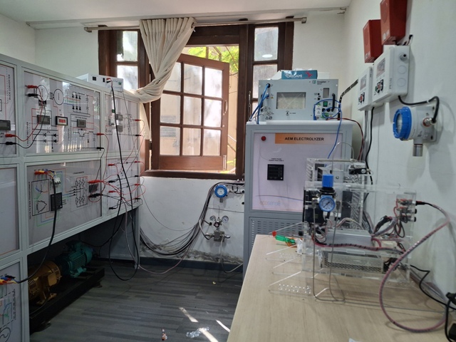
B. Electrolyzer Integration
At the heart of the lab’s hydrogen production system is an
AEM Electrolyzer, integrated at the Point of Common Coupling (PCC) within the
microgrid. Key features of the electrolyzer system include:
·
Distilled Water Supply: Delivered
via a specialized high-pressure, low-volume pump to ensure optimal hydrogen
production.
·
Hydrogen Storage: The
produced hydrogen is dried using a hydrogen dryer, then safely stored in
high-pressure hydrogen cylinders.
C. Hydrogen Utilization
The stored hydrogen serves as a vital resource for powering
the microgrid. It is supplied to the fuel cell, where it is converted into
clean electricity, completing the hydrogen energy cycle.
D. Comprehensive Safety Measures
Ensuring safety is paramount in a facility dealing with
hydrogen. The lab is equipped with advanced safety protocols to guarantee
secure operations at all times:
D.1 Relay Systems:
Each source and load within the microgrid is connected
through relays, allowing for immediate shutdown of all equipment in the event
of a hydrogen leakage.
D.2 Hydrogen Leak Detectors:
The lab features three strategically placed hydrogen leak
detectors. In case of leakage detection, the following measures are
automatically executed:
·
Solenoid Valve Shutdown:
Hydrogen supply to the fuel cell is stopped by shutting off the solenoid valves
at the manifold. Electrolyzer Safety: The flow of hydrogen from the
electrolyzer to the storage cylinders is halted.
These rigorous safety measures create a secure environment
for researchers and students, fostering innovation while ensuring their
well-being.